
"Simon's a computer, Simon has a brain, you either do what Simon says or else go down the drain!" Nearly everyone has heard of the Simon Game first introduced in 1978 by Milton Bradley Company, now a division of Hasbro Toy Company. It is a game of memory skill played against a computer, with selectable game modes that can challenge the sharpest of minds. SimonSense is a variation of the Simon Game, but uses LEDs as buttons instead of mechanical buttons...
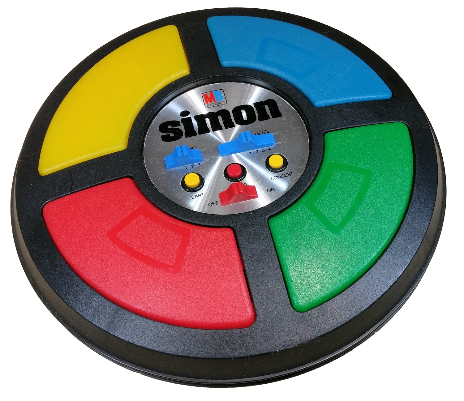
The original game has large red, yellow, blue and green buttons which can be lit up an incandescent lamp mounted behind it. Simon also incorporates a speaker that plays a specific tone for each button. To play, first turn the game on and press the start button. The computer then lights a button and plays its tone. You must follow by pressing that same button. The computer then plays the first button then randomly activates a second button. You must follow by pressing the two buttons in sequence. The computer continues the randomly adding and activating a third button to the button sequence.... etc, etc, etc. The button sequence gets longer and harder to remember, and you only have a certain amount of time to complete the sequence. If you persist, you win and hear the win sound! Else, you get a bonking sound. This is the basic game play of Simon, but the switches on the panel allow you to select more complex game play, or even play with other players. Many variations of Simon Game have been produced, along with many clones. I have even seen versions of the 1978 Simon Game with different placements of the colored buttons. This one pictured in this blog is RYBG, but most of them on EBay are YGRB. Mine is RBYG, but the picture on the box it came in is YGRB. What's going on here? Maybe the factory quality control was not so perfect. The buttons are interchangeable, however, if you want to disassemble Simon.
Let's change the subject for a moment and describe how some basic electronic components can be used in the opposite of their intended design. Take for example a DC Brush Motor. When you hook up the motor to a DC supply, the motor starts to turn clockwise. Reverse the polarity of the DC supply to the motor and it turns counter clockwise. But that is not the "opposite" I am talking about. Now take a simple Blue LED (my fav LED color:-) and connect the anode to the positive lead of the motor. Connect the cathode lead directly to the negative lead of the motor. Now spin the motor with your fingers really fast in the clockwise direction. What happens? Yep... the LED lights up! Why, because a DC motor is designed much like a DC generator. However, a DC motor most likely performs best when used in its intended designed purpose.
How about another... a magnetic speaker is typically designed with a cylindrical wire coil wound over a small cylindrical tube and is called a "Voice Coil". One end of the Voice Coil is typically mounted to a paper cone. Applying a rapidly changing polarity of current to the Voice Coil produces a rapidly changing north/south magnetic field at the ends of the Voice Coil. The Voice Coil cylinder is partially slide over a strong cylindrical solid core magnet. When the Voice Coil magnetic field interacts with the solid core magnetic field, the Voice Coil moves towards or away from the core magnet causing the cone to produce varying air pressure and the sounds we hear. This combination of Voice Coil and solid magnet is called a "Voice Coil Actuator". So what's this all got to do with our discussion of using something in the opposite of its design intent? Well if a speaker is hooked up to a phonograph or microphone input of a stereo system and you tap on the speaker cone, you will hear a thump! That's because a Voice Coil manually moved back and forth over the core magnetic produces a changing current in the coil. Conceivably a speaker could be used as a microphone, but it would be a very very poor microphone since it was not designed for that purpose.
This brings us back to "SimonSense" and using individual Light Emitting Diodes (LEDs) as buttons in this project. The primary purpose of LEDs are to emit light, and they come in four primary colors red, green, blue and yellow. There are many LED variations and purposes like infrared, ultra violet and laser to name a few, but individual RGBY LEDs are the most common. Simply stated LEDs convert the movement of electrons into photons... visible and sometimes blindingly bright photons! Red, green and yellow LEDs were introduced in 1962. Blue LEDs straggled behind, first being introduced in 1972, and winning a Physics Nobel Price. RGY LEDs typically operate at around 2 volts DC at 20 milliamps applied between the anode(+) and cathode(-) leads. Blue is the odd ball, typically operating around 3 volts at similar current levels. LEDs have been used as indicators in all sorts of ways. However, did you know an LED can also convert photons into electrons? Try this experiment. Get a very strong flashlight and shine it directly into the lens of a yellow LED and measure the voltage at the LED anode(+) and cathode(-) pins. You should read maybe 1 volt. RGB LEDs will do the same, but since they are far less sensitive to white light, the measured voltage levels are orders of magnitude less. Don't expect to power anything from an LED, since it produces only picoamps of current. The results of this experiment should not be surprising, since photo diodes are designed specifically to measure light, and photo cells specifically designed to produce electricity. It is interesting to note that diodes, transistors and integrated circuits are encapsulated in opaque packages to eliminate the affects of light. Another property of the individual LED is that when reversing the voltage applied to the anode and cathode, a small capacitance can be measure. This capacitance may be anywhere from a few picofarads to several hundreds picofarads depending on its design and applied voltage. Varicaps or varactors are diodes specifically designed for this purpose. So, LEDs can convert electrons into photons and photons into electrons... and they can also serve as a small capacitor! We now have enough LED trivia to do something unique.

of the TI TMS1000 4-bit Microcontroller
Believe it or not, the original Simon Game incorporated a "Nibble" processor! Yep, it was a modified version of the Texas Instruments 4-bit TMS1000 microcontroller marked MP3300MLL, running at 400 Kilohertz. Intel introduced the first 4-bit 4004 Central Processing Unit (CPU) in 1971, and TI introduced the first 4-bit TMS1000 microcontroller (MCU) in 1974. Did you know it takes two nibbles to make a "byte"... 8-bits that is :-) Technology has advanced in amazing ways since the electron tube era I first played in. Tubes were rapidly replaced after the invention of the transistor by Bell Labs in the late 50's. The discovery of the transistor and use of semiconductors then birthed the integrated circuit. The 4004 CPU has about 2000 transistors on a single Integrated Circuit

(IC) and the TMS1000 about 8000. A genuine vintage C4004 can fetch several hundreds and even thousands of dollars by collectors. Today over 30+ billion transistors can be packed in to a single IC, and can run at Gigahertz speeds! SimonSense uses the ATmega328p 8-bit microcontroller running a 16 Megahertz. The ATmega328p was made ubiquitous by the Arduino UNO. Obviously this 8-bitter with 16 MIPS is overkill for the needs for the vintage Simon Game, but SimonSense makes use of the MIPS by doing thousands of 32-bit floating point operations per second. By the way, if you want some reading material to put you to sleep, just download the ATmega328p "Complete Datasheet" and start reading. It's only 660 pages long! And if you are a glutton for punishment, next download the ATmega328p "Assembly Instruction Set Manual" that is only 190 pages... surely you'll be snoozing by the end of that!
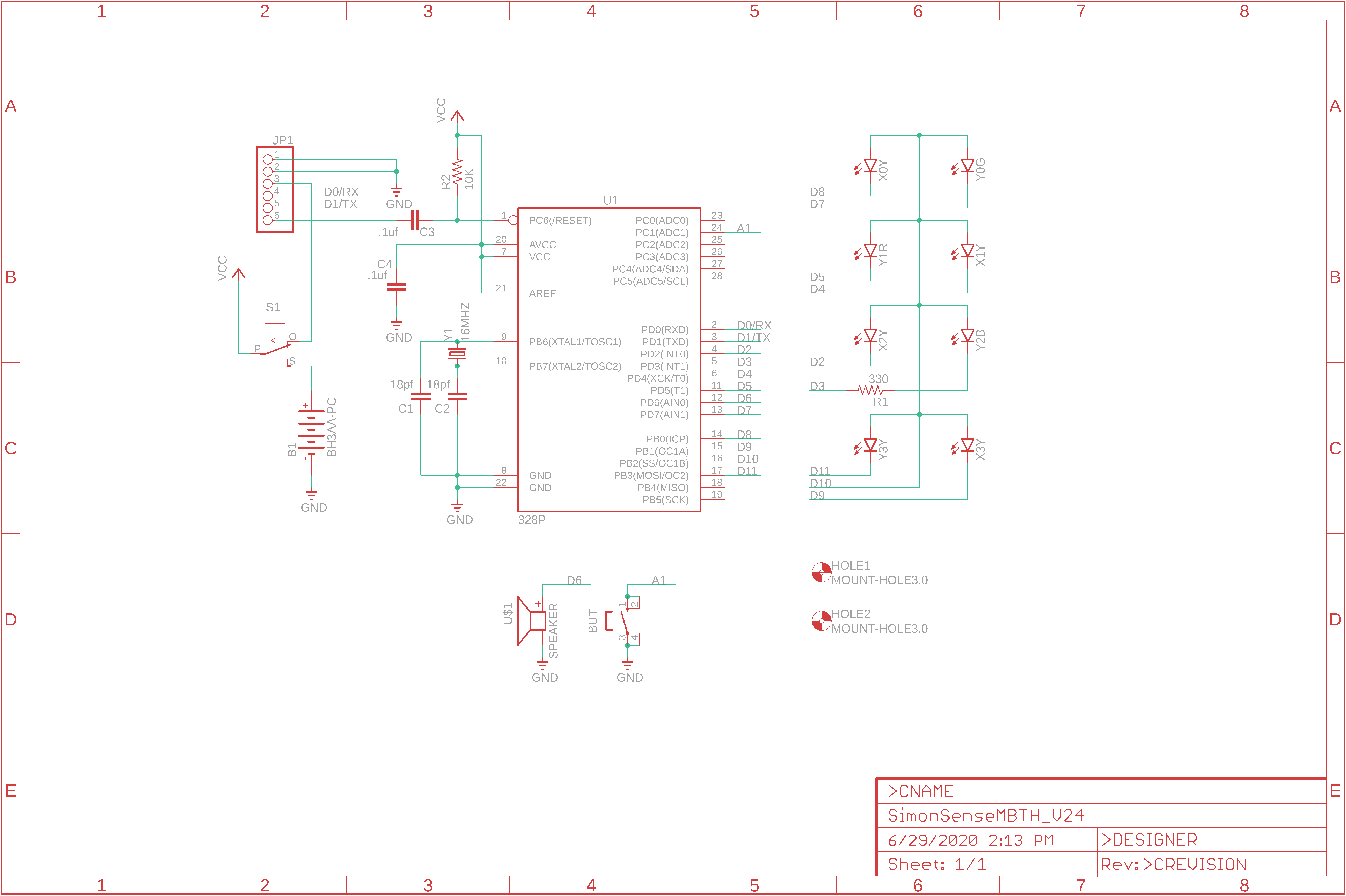
The basic process of using LEDs as buttons is quite simple, however, the SimonSense code is a complex state machine that dynamically calculates ambient light levels, averages shadow trigger points and button hysteresis, not to mention executing the game and blinking LEDs ON/OFF and playing tones. The LED Sensor Button diagram shows the charging then discharging of the LED's reverse biased capacitor. Microcontroller pins connected to the LED cathode/anode can place the LED in forward or reverse biased mode (see schematic). Once the LED is quickly charged in reversed biased mode (cathode=5v, anode=ground), the micro changes the cathode pin to an input and starts a discharge timer. Once the LED capacitor discharges below the 2.5v HIGH to LOW threshold point of the micro digital input pin, the discharge period is calculated in microseconds. If the light level on the LED is reduced by placing a finger over the LED (blocking light), then the LED capacitor takes longer to discharge resulting in a longer discharge period. This difference in short and long discharge periods averaged over many cycles is what is used to determine if an LED button was pressed or not. The microcontroller can turn on an LED by setting the anode/cathode pins in a forward biased mode. The Sensor Array Graph shows that yellow LEDs discharge faster than green and red. In typical ambient classroom lighting a yellow LED discharges typically under 20 ms, and with finger shadow over the LED it is over 100 ms. A blue LED takes over 1 second to discharge in ambient lighting, so its not very responsive or practical to use. Note that light photons are converted to electrons in the opposite polarity the LED capacitor was charged. So more light makes it discharge faster. A clear lens yellow LED that has a narrow 30 degree focal lens works even better, which is what SimonSense uses.
So hears the deal... SimonSense works much like the Simon basic game mode, but uses LEDs as buttons instead. The ATmega328p micro is programmed to rapidly execute logic to either emit light or detect light. The outer rim clear lens LEDs are used as light sensors, but they can also light up. The inner rim colored LEDs represent the button colors. The first time my son Jason tried SimonSense, it took him 14 tries to get it right! It is even trickier than the original Simon because the button is responding to changes in light levels, not finger pressure. If you don't pay attention to the shadow of you finger, you will mess up and "go down the drain" with a bonk, else you win and "Fan Fair" is played... but with a piezo not a trumpet! I've been tempted to take it to a bar and challenge someone to a competition after a few drinks :-) It would be hilariously frustrating to play and fun to watch. I will probably drive those at the bar crazy with all the noise! That's why SimonSense has an audio silence button! The SimonSense program is developed and uploaded using Arduino IDE using an the 6-pin FTDI cable. When you first turn on SimonSense, it goes through a quick ambient light level calibration. When you hear the 3 beeps and transitions to the player attract mode. You start the game by triggering any LED. The SimonSense video demonstrates how LED processing slows down when you wave your hand over the LEDs during the calibration mode.

Add new comment